

| Place of Origin: | China |
|---|---|
| Brand Name: | CANYI |
| Certification: | RoHS |
| Model Number: | bluetooth 5.0 pcb board |
| Minimum Order Quantity: | 200PCS |
| Price: | Negotiated |
| Packaging Details: | Boxed |
| Delivery Time: | 1 - 2 Weeks |
| Payment Terms: | Telegraphic Transfer in Advance (Advance TT, T/T) |
| Supply Ability: | 15,000,000PCS Per Day |
| Model Number: | Bluetooth Transmission Pcb Board | Application: | Computer |
|---|---|---|---|
| Supply Voltage: | 5V | For Arduino STM: | Electronic Module |
| High Light: | 2.4G Bluetooth Transmission Pcb Board,5mA Bluetooth Transmission Pcb Board,Ble5.0 Transparent Transmission Module |
||
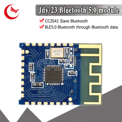
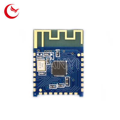
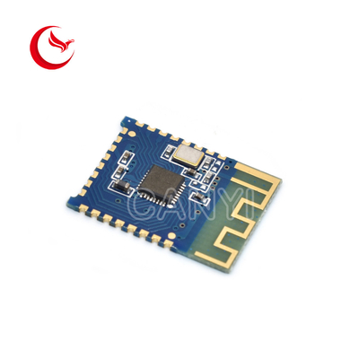
Product Introduction
| JDY-23 product parameters | |
| model | JDY-23 |
| Working frequency | 2.4G |
| Transmit power | 4db(maximum) |
|
Communication Interface
|
UART |
|
Operating Voltage
|
1.8V – 3.6V |
| Operating temperature | -40℃ - 80℃ |
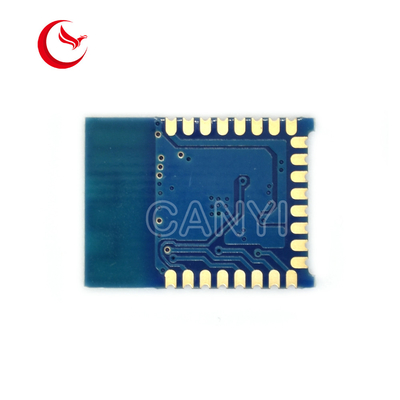
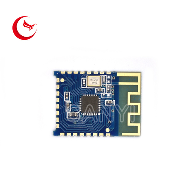
| antenna | Built-in PCB antenna |
|
Receiving sensitivity
|
-97dbm |
| Transmission distance | 60 M |
|
Master-slave support
|
Slave |
| Module size | 19.6 * 14.94 *1.8 mm(Length, width and height) |
| Bluetooth version | BLE 5.0(Compatible with BLE4.0, BLE4.2) |
| Awakening state current | 800uA(Broadcast) |
| Light sleep state current | <50uA (Broadcast) |
|
Deep sleep current
|
9uA (No broadcast) |
|
Instruction parameter saving
|
Parameter configuration power-down data is saved |
| SMT soldering temperature | <260℃ |
| rf-TX/RX peak current | 5mA |

Pin function description
| Features | Description | |
| 1 | VCC | Power supply (1.8-3.6V) |
| 2 | NULL | No |
| 3 | NULL | No |
| 4 | OUTPUT1 | IO1 output pin (support APP control high and low level) |
| 5 | OUTPUT2 | IO2 output pin (support APP control high and low leve) |
| 6 | STAT | Connection status pin, connected high, not connected low |
| 7 | INPUT7/PWM4 |
INPUT7 mode: For the input pin, the APP can read the status of this pin. PWM mode: PWM4 output pin, APP can control PWM4
pulse width
The default is: INPUT7 mode
|
| 8 | OUTPUT3 | IO3 output pin (support APP control high and low level) |
| 9 | OUTPUT4 | IO4 output pin (support APP control high and low level) |
| 10 | OUTPUT5 | IO5 output pin (support APP control high and low level) |
| 11 | INPUT6/PWM3 |
INPUT6 mode: For the input pin, the APP can read the status of this pin. PWM mode: PWM3 output pin, APP can control PWM3
pulse width
The default is: INPUT6 mode
|
| 12 | INPUT5/PWM2 |
INPUT5 mode: For the input pin, the APP can read
the status of this pin.
PWM mode: PWM2 output pin, APP can control PWM2
pulse width
The default is: INPUT5 mode
|
| 13 | OUTPUT6 | IO6 output pin (support APP control high and low level) |
| 14 | OUTPUT7 | IO7 output pin (support APP control high and low level) |
| 15 | INPUT4 | For the input pin, the APP can read the status of this pin. |
| 16 | EINT2 | Interrupt input pin (in the connected state, press to actively send IO status to APP) |
| 17 | ALED | Broadcast indicator pin |
| 18 | INPUT3/PWM1 |
INPUT3 mode: For the input pin, the APP can read the status of thi pin. PWM mode: PWM1 output pin, APP can control PWM1
pulse width
The default is: INPUT3 mode
|
| 19 | TXD | Serial output pin (TTL level) |
| 20 | RXD | Serial input pin (TTL level) |
| 21 | EINT1 | Interrupt input pin (in the connected state, press to actively send IO status to APP) |
| 22 | PWRC |
Sleep wake-up pin, active low
In the connected state, the AT command can be pulled
low through the PWRC pin.
|
| 23 | RST | Reset pin, active low |
| 24 | GND | Power ground |
| sequence | instruction | effect | Master/Slave | default |
| 1 | AT+VER | version number | S | JDY-23-V2.1 |
| 2 | AT+RST | Soft reset | S | - |
| 3 | AT+DISC | AT command disconnected | S | - |
| 4 | AT+STAT | 00 | ||
| 5 | AT+MAC | MAC address | S | - |
| 6 | AT+BAUD | Baud rate | S | 9600 |
| 7 | AT+SLEEP | Sleep | S | |
| 8 | AT+NAME | Broadcast name | S | JDY-23 |
| 9 | AT+STARTEN | Boot sleep or wake up | S | 0(开机唤醒) |
| 10 | AT+ADVIN | Broadcast interval | S | 1(200mS) |
| 11 | AT+HOSTEN | Slave mode or IBEACON working mode | S | 0(从机) |
| 12 | AT+IBUUID | IBEACON's UUID | S | FDA50693A4E24FB1AFCFC6EB07647825 |
| 13 | AT+MAJOR | IBEACON's MAJOR | S | 10 |
| 14 | AT+MINOR | IBEACON's MINOR | S | 7 |
| 15 | AT+IBSING | Signal calibration at 1 meter | 0x32 | |
| 16 | AT+ALED | Broadcast LED indicator switch | 1 | |
| 17 | AT+IBPWR | IBEACON SING value | S | 50 |
| 18 | AT+DEFAULT | reset | S | - |
| 19 | AT+POWR | Transmit power | S | 8 |
| 20 | AT+ENLOG | Serial output LOG switch | S | 0 |
| 21 | AT+MTU | Set the serial port to the APP to send a long number of packets | S | 1 |
| 22 | AT+BATT | Set battery | S | 0 |
![]()

![]()

